Pipeline Execution Engine
One-Sentence Definition
The Pipeline execution engine is the parallel execution model that has replaced the volcano model in Doris since 3.0. It draws on the Pipeline implementation described in the Hyper paper and splits a query into Pipelines and PipelineTasks that can run in parallel. This fully releases multi-core CPU power and limits the number of query threads, thereby solving the thread bloat problem.
Overview Checklist
Before reading this article, you should be familiar with the following points:
- The Pipeline execution engine has fully replaced the original volcano model since Doris 3.0.
- Based on the Pipeline model, Doris implements parallel processing of Query, DDL, and DML statements.
- For detailed design, implementation, and effects, refer to the following two DSIPs:
Physical Plan
To understand the Pipeline execution model, you need to first understand two core concepts in the physical query plan: PlanFragment and PlanNode. The following example SQL is used for illustration:
SELECT k1, SUM(v1) FROM A,B WHERE A.k2 = B.k2 GROUP BY k1 ORDER BY SUM(v1);
Logical Plan
The FE first translates this SQL into the following logical plan, where each node in the plan is a PlanNode. For the meaning of each Node type, refer to the introduction on viewing the physical plan.
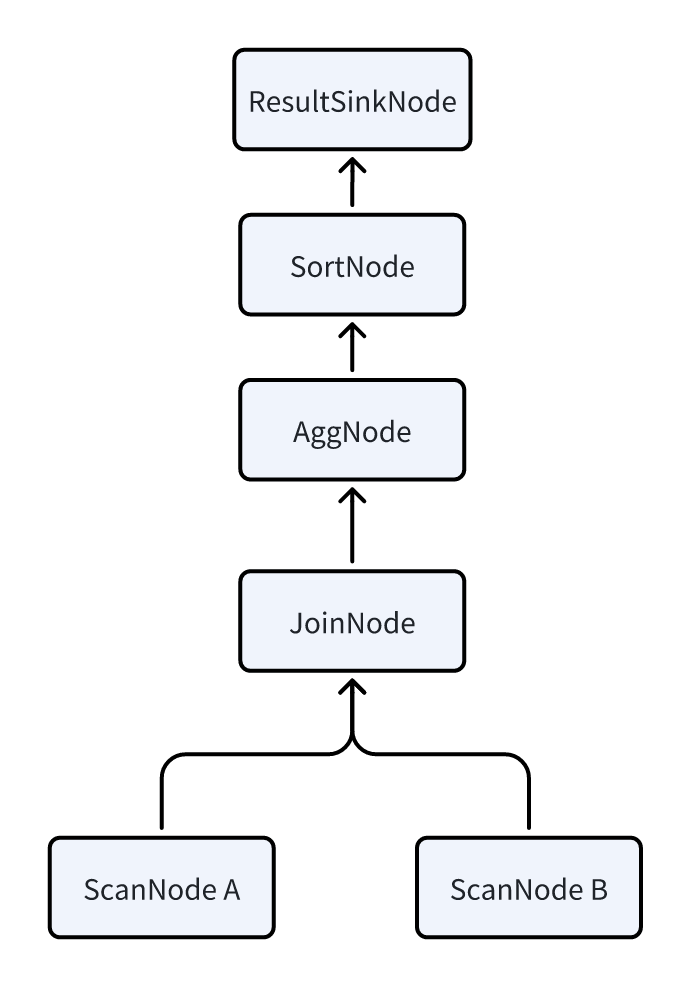
Physical Plan
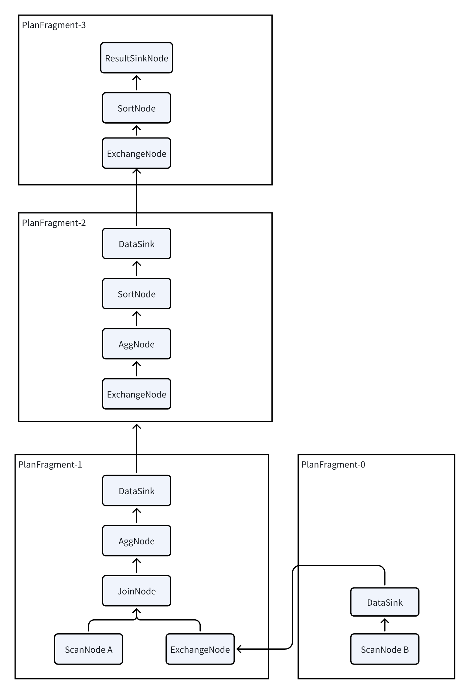
Because Doris uses an MPP architecture, every query tries to involve all BEs in parallel execution to reduce query latency. The logical plan therefore needs to be split into a physical plan:
- Insert
DataSinkandExchangeNodeinto the logical plan. These two Nodes complete the data Shuffle between multiple BEs. - After splitting, each PlanFragment contains a portion of PlanNodes and can be sent to a BE as an independent task.
- After a BE finishes computing the PlanNodes inside a PlanFragment, it shuffles the data to other BEs through
DataSinkandExchangeNodeto continue computation.
Three-Layer Planning Structure
Doris planning is divided into the following 3 layers:
| Layer | Name | Description |
|---|---|---|
| 1 | PLAN (execution plan) | A SQL statement is translated by the execution planner into an execution plan, which is then run by the execution engine. |
| 2 | FRAGMENT (execution fragment) | Doris is a distributed execution engine. A complete execution plan is split into multiple single-machine execution fragments. A FRAGMENT represents a complete single-machine execution fragment, and multiple FRAGMENTs together make up a complete PLAN. |
| 3 | PLAN NODE (operator) | The smallest unit of an execution plan. A FRAGMENT consists of multiple operators, and each operator is responsible for a specific execution logic, such as aggregation or join. |
Pipeline Execution Model
PlanFragment is the smallest unit of execution task that the FE sends to a BE. A BE may receive multiple different PlanFragments belonging to the same Query, and each PlanFragment is processed independently.
After receiving a PlanFragment, the BE processes it as follows:
- Split the PlanFragment into multiple Pipelines.
- Start multiple PipelineTasks to achieve parallel execution.
- Improve query efficiency.
Pipeline
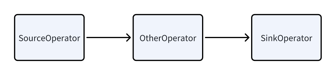
A Pipeline consists of the following parts:
- One SourceOperator: represents reading data from outside. It can be a table (OlapTable) or a Buffer (Exchange).
- Multiple other Operators in the middle.
- One SinkOperator: represents data output. It can be shuffling data over the network to another node (such as
DataStreamSinkOperator), or outputting to a HashTable (such asJoinBuildHashTablefor the Agg operator).
Dependencies Between Pipelines (Dependency)
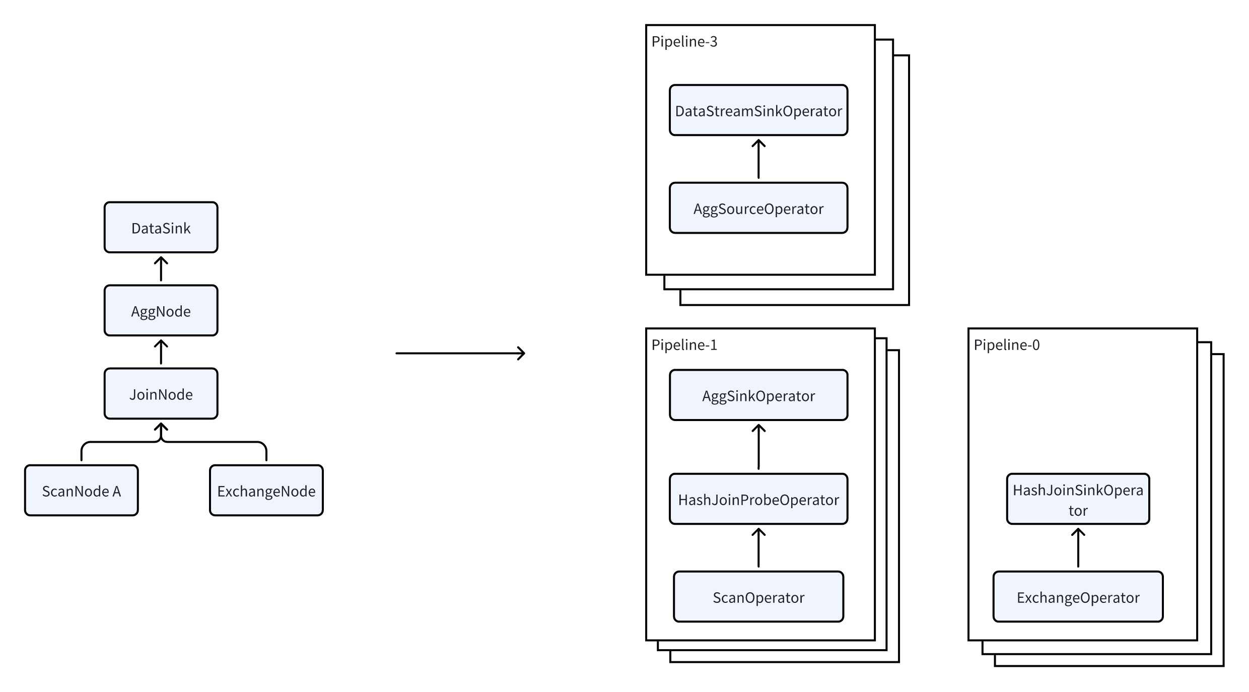
Multiple Pipelines have dependency relationships with each other. Take JoinNode as an example. It is actually split into 2 Pipelines:
- Pipeline-0: reads data from Exchange to build the HashTable.
- Pipeline-1: reads data from the table to perform the Probe.
The relationship between these two Pipelines is as follows:
- The execution of Pipeline-1 depends on the completion of Pipeline-0.
- This dependency relationship is called Dependency.
- Once Pipeline-0 has finished running, it calls the Dependency's
set_readymethod to notify Pipeline-1 that it can run.
PipelineTask
A Pipeline is in fact still a logical concept rather than an executable entity. To actually execute it, the Pipeline must be instantiated as multiple PipelineTasks:
- The data to be read is allocated to different PipelineTasks, ultimately enabling parallel processing.
- Multiple PipelineTasks of the same Pipeline have exactly the same Operators. The difference lies in the state of the Operators (for example, the data being read is different, the HashTable being built is different, and so on). These different states are called LocalState.
- Each PipelineTask is finally submitted to a thread pool to execute as an independent task.
Under this Dependency-driven mechanism, multi-core CPUs can be utilized more effectively to achieve full parallelism.
Operator
In most cases, each Operator in a Pipeline corresponds to one PlanNode, but there are some special operators that are exceptions:
| Original PlanNode | Operators after splitting |
|---|---|
| JoinNode | JoinBuildOperator + JoinProbeOperator |
| AggNode | AggSinkOperator + AggSourceOperator |
| SortNode | SortSinkOperator + SortSourceOperator |
Splitting principle: For some breaking operators (operators that need to collect all data before they can compute), the part that ingests data is split into Sink, and the part that fetches data from this operator is called Source.
Scan Parallelization
Scanning data is a very heavy IO operation. It needs to read large amounts of data from the local disk (in data lake scenarios, data has to be read from HDFS or S3, which has even higher latency). To optimize scan efficiency, Doris introduces a parallel scan technique in ScanOperator:
- The ScanOperator dynamically generates multiple Scanners.
- Each Scanner scans approximately 1 million to 2 million rows of data.
- Each Scanner performs the corresponding data decompression, filtering, and other computation tasks while scanning the data.
- The Scanner sends data to a DataQueue for the ScanOperator to read.
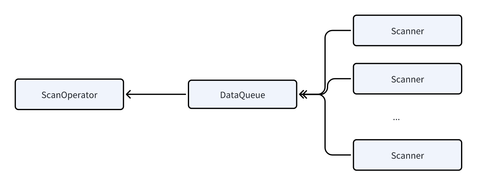
Benefit: Parallel scanning effectively avoids the problem where some ScanOperators take too long to execute due to unreasonable bucketing or data skew, which would otherwise drag down the entire query latency.
Local Shuffle
In the Pipeline execution model, Local Exchange acts as a Pipeline Breaker. It is a technique that redistributes data locally to each execution task.
It serves the following purposes:
- Evenly distributes all data output by the upstream Pipeline to all Tasks of the downstream Pipeline using a certain method (HASH or Round Robin).
- Solves data skew problems during execution.
- Frees the execution model from being constrained by data storage and the plan.
Working Example
The following uses Pipeline-1 from the earlier example to illustrate how Local Exchange avoids data skew.
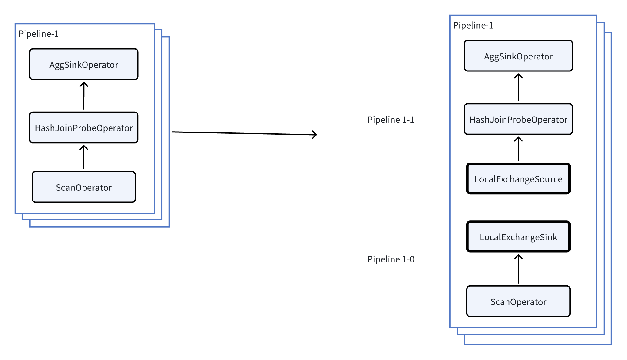
As shown in the figure above, by inserting a Local Exchange into Pipeline 1, Pipeline 1 is further split into:
- Pipeline 1-0
- Pipeline 1-1
Assume that the current concurrency equals 3 (each Pipeline has 3 tasks), each task reads one bucket from the storage layer, and the row counts in the 3 buckets are 1, 1, and 7 respectively. The execution change before and after inserting the Local Exchange is as follows:
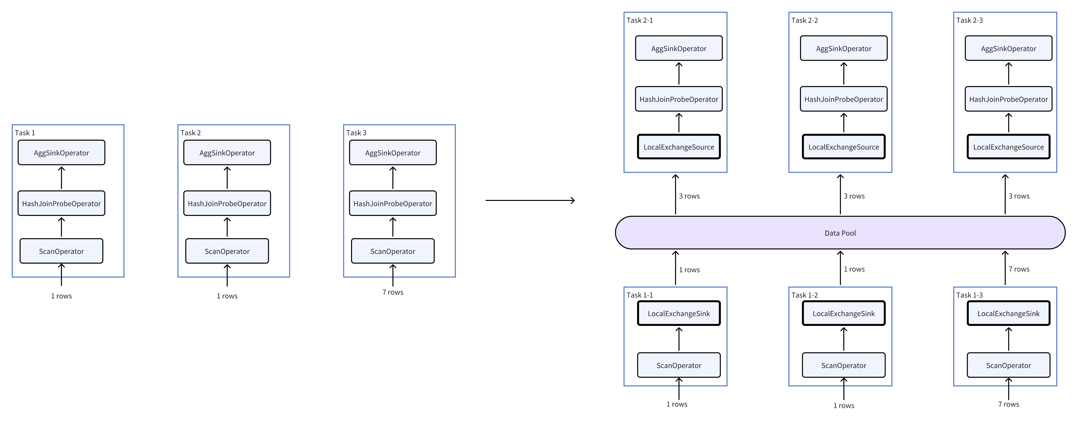
As the right side of the figure shows, the amount of data that the HashJoin and Agg operators need to process changes from (1, 1, 7) to (3, 3, 3), thus avoiding data skew.
Planning Rules
In Doris, whether Local Exchange is planned is determined by a set of rules. For example, when a query contains time-consuming operators such as Join, aggregation, or window functions, Local Exchange is used to avoid data skew as much as possible.